Home > Products Categories > Other Product
Condensate Pots
Working Principle
There are several factors that impact the reliability, performance, longevity, and maintenance requirements for the condensate Pots system. Some of these factors are listed below:
- Condensate line sizing that factors condensate liquid and flash steam quantities.
- Location of the condensate line with respect to the process equipment.
- Locations of the condensate branch line connection into the main condensate headers.
- Insulation techniques
An important factor to increase overall steam system efficiency is to maximize the temperature of the returning condensate. This permits high thermal cycle efficiency for the overall steam system.
Energy
Condensate contains a high percentage of the energy (typically 16%) used to produce steam. Recover and return all possible condensate back to the boiler plant as hot as possible. Accept no component failure within three years of operation. Install components with maintenance in mind. Size condensate lines understanding the medium will be two (2) phase flow. Utilize connections that minimize leaks. Understand the various pressures of condensate returns available in order to design the piping system with proper flow. Remember to allow for pressure gauge installations throughout the system. These inexpensive devices are a key aid in troubleshooting the steam and condensate system. Following these rules will help to ensure a reliable and long life span of the condensate system.
Correct Identification of Condensate Type
The first step is to understand and identify the type of the condensate line.
Gravity
• This describes all process equipment with a modulating inlet steam valve and a very low steam pressure application that the condensate return line must be at or close to atmospheric conditions. Therefore, the condensate drains by gravity to a vented (atmospheric) condensate collection tank.
Low pressure return
• Condensate return that is less than 15 psig.
Medium pressure
• Condensate return that is between 15 and 100 psig.
High pressure return
• Condensate return piping system pressures of 100 psig or higher
Most of the condensate system problems are from the location of the condensate lines in relationship to the heat transfer equipment, steam trap and other drainage type devices.
Materials Condensate Pots
The condensate Pots themselves are potentially subjected to a damaging corrosive element in the form of carbonic acid. The recommended material to use for a condensate system is stainless steel. However, understanding the cost limitations to an all stainless steel condensate system, there are other alternatives. Condensate piping should be at a minimum, schedule 80, carbon steel. Stainless steel greatly enhances the pipes ability to withstand the corrosive attack and therefore can provide a long reliable operational life. If carbon steel piping is used for economical consideration, schedule 80 pipe is used because of the heavier wall thickness which prolongs the life of the pipe in a corrosive environment.
Measurement Accuracy
The primary use for condensate pots is to maximising the accuracy of differential pressure flow measurement on steam (or vapour) applications.They are used to ensure that the condensation of steam in the impulse lines does not impair the ability to accurately sense differential pressure fluctuations and to minimise gauge line error because of differences between pairs of impulse lines.
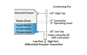
The theory of operation for condensate pots is that between the process taping and the pot is steam vapour. Between the pot and the differential pressure transmitter is water (liquid) which eliminates any measurement errors due a liquid/vapour mix at the measurement device.
In order for this to work correctly both high pressure (HP) and low pressure (LP) impulse lines should be the same length.
Thus, eliminating pressure head errors. One condensate pot will be required for each impulse line.
There are several factors that impact the reliability, performance, longevity, and maintenance requirements for the condensate piping system. Some of these factors are listed below :
Condensate line sizing that factors condensate liquid and flash steam quantities.
- Location of the condensate line with respect to the process equipment.
- Locations of the condensate branch line connection into the main condensate headers.
- Insulation techniques
An important factor to increase overall steam system efficiency is to maximize the temperature of the returning condensate. This permits high thermal cycle efficiency for the overall steam system.
Application Condensate Pots
Condensate pot is as an additional tool used before the flow transmitter. The purpose of the condensate pots installed is to separate the steam from the flow so that the measurement is more accurate, where this steam can interfere with the measurement process.
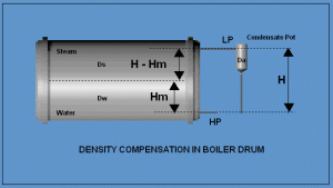
The following is an example of a condensate pot application diagram combined with a pressure transmitter as a measuring tool.


- Features
- Technical Data
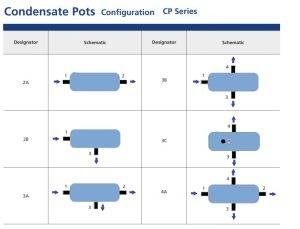
- Configuration
-
CP Series Condensate Pots
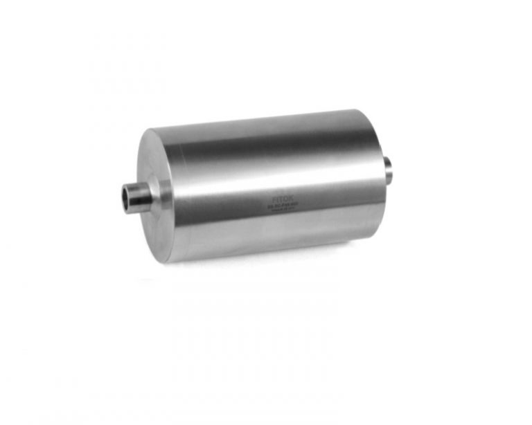
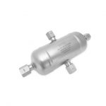
CP series condensate pots are designed to trap condensate and foreign matter that may accumulate in gaseous service lines, and preventing damage to the sensitive instrumentation components. Pots with more outlet ports for applications where foreign material should be trapped and drained preventing damage of the manifolds and transmitters are also available.
Features
◎ Use as liquid or condensate traps, seal pots, vapor chambers and knockout pots.
◎ Chambers are made from seamless pipe and weld caps.
◎ Full-penetration gas tungsten arc -weld construction to ensure great strength and leak-tight performance.
◎ Five pressure ratings optional
Technical Data
◎ Working pressure up to: Class 2500
◎ Socket weld connection as per ANSI B16.11
◎ Butt welding ends as per ANSI B16.9
◎ NPT as per ANSI B1.20.1 taper pipe thread
◎ All chambers are factory tested fully prior to shipment
◎ Standard material of construction: 316 SS, 304 SS, Carbon steel
◎ Pipe schedule: 40, 80, 160, XXS seamless steel
◎ Variety of end connections available
Connecting into the Condensate Pots
It is imperative that all condensate branch lines are connected into the top dead center of the main condensate header on a horizontal plane. This cannot be overstated and there is no exception to this rule.
Connecting into the Condensate Header
It is imperative that all condensate branch lines are connected into the top dead center of the main condensate header on a horizontal plane. This cannot be overstated and there is no exception to this rule.
Improper condensate connections are listed below:
Connection to the bottom of a condensate header.
Connection to the side of a condensate header.
Connection to a vertical condensate header.
The condensate connections listed above will cause system problems. The primary issue or problem will be water hammer
that will result from the improper connection location. Flash steam introduced to the main condensate
header due to an improper connection location will interact with cooler condensate causing waterhammer.
Waterhammer is the leading cause of premature component failures in a steam/condensate system.
Vessels
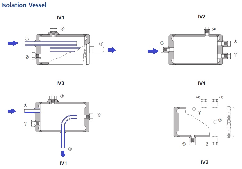
SV series vessels are designed to trap condensate and foreign matter that may accumulate in gaseous service lines, and purify gas media. They are often classified as condensation, isolation and separation vessels in different applications, widely used in refineries, power plants, petro-chemical and other process industries.
