
Diaphragm Regulators High Flow
RDGN Series
Introduction
RDGN Series High Flow Diaphragm Regulators feature a single-stage pressure reduction design with a combination of metal diaphragm and free poppet for excellent sensitivity and stable outlet pressure. The reset spring configuration maintains stable and low outlet pressure, even under high flow conditions, making these regulators ideal for various gas media with high flow.
Features Diaphragm Regulators High Flow RDGN Series
◎ Large diameter diaphragm offers enhanced pressure sensitivity
◎ Metal-to-metal seal between valve body and diaphragm provides ensured sealing performance
◎ Reinforced diaphragm design extends diaphragm service life
◎ The bonnet includes a captured vent port, allowing media to be vented to a designated location in the event of accidental diaphragm rupture
|
Port Size |
3/4″ or 1″ |
|
Max. Working Pressure |
500 psig (34.5 bar) |
|
Outlet Pressure Range |
0 ~ 15 psig (0 ~ 1.0 bar) |
|
|
0 ~ 30 psig (0 ~ 2.1 bar) |
|
|
0 ~ 75 psig (0 ~ 5.2 bar) |
|
|
0 ~150 psig (0 ~ 10.3 bar) |
|
|
0 ~ 200 psig (0 ~ 13.8 bar) |
|
|
0 ~ 1800 psig (0 ~ 124 bar) |
|
Flow Coefficient (Cv) |
1.8 |
|
Working Temperature |
-40 ~ 165 °F (-40 ~ 74 °C) |
|
SPE (Supply Pressure Effect) |
4.5 psig per 100 psig source pressure change |
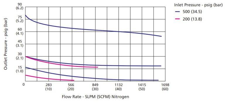
Flow Data
Process Specification Sensitive Diaphragm Regulators
| Process Specification | Special Cleaning and Packaging Process (FC-02) | Ultra High Purity Process (FC-03) |
|---|---|---|
|
Material
|
316L SS, Brass
|
316L SS |
|
Wetted Surface Roughness |
Face Seal Connection or Butt Weld Connection:
Ra 20 in. (0.5 m)
Threaded Connection or Tube Fitting Connection:
Ra 32 μin. (0.8 μm) |
Face Seal Connection and Butt Weld Connection:
Ra 10 in. (0.25 m) |
|
Polishing Process |
Machine Finished |
Electropolished |
|
Assembly Environment |
In specially cleaned areas |
ISO Class 4 (FS 209E Class 10 equivalent) cleanroom
|
|
Packaging |
Double bagged |
Double bagged in cleanroom |
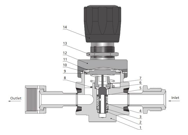
Major Materials of Construction Diaphragm Regulators High Flow RDGN Series
| Item | Component | Material/Specification |
|---|---|---|
|
1 |
Body |
316L SS or Brass |
|
2 |
Guide Ring
|
PTFE/ASTM D1710 |
|
3 |
Spring Seat
|
316L SS |
|
4 |
Poppet Spring |
316L SS or Alloy X-750 |
|
5 |
Lift Poppet
|
316L SS
|
|
6 |
Seat |
PCTFE/ASTM D1430 or PTFE/ASTM D1710 |
|
7 |
Seat Retainer
|
316L SS |
|
8 |
Reset Spring |
316 SS |
|
9 |
Buffer Plate |
316L SS |
|
10 |
Light-Duty Retainer |
316L SS |
|
11 |
Diaphragm |
316L SS/ASTM A240 |
|
12 |
Bonnet |
304 SS/ASTM A479 or Brass
|
|
13 |
Panel Nut
|
304 SS/ASTM A479
|
|
14 |
Handle |
ABS |
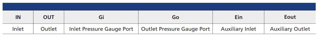
Porting Configuration Symbol
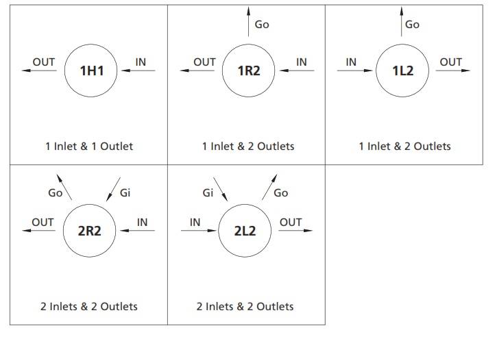
Porting Configuration Symbol
Notes:
1. IN and OUT are the inlet and outlet ports for connecting the valve to the system. so that other Port should not be used for system connections.
2. Porting configuration is viewed from the top.