Needle Valve basic function :
Needle Valve are one of the oldest and most basic mechanical components in fluid handling systems. Although there are many variations in the types and designs of valves, most perform one of two basic functions of valve :
Isolation :The valve is function to open or closed; its function is work is to turn the flow on or off by connecting, it thus isolating it from the rest of the system.
Regulation :The valve is function to regulates the rate of flow through the system and it usual is neither fully open nor fully closed.
How Needle Valve Work
- Isolation
Isolation (shut-off) Valve which Screw actuation allows the valve to opened gradual and the thread stem is requires three or four turns of the handle to open and close the valve. For exceptionally high pressures general above 10.000 Psig (690 bar) with a special variation of needle valves has been design. Although similar to other needle valves for this type of valves contain unique design features with materials specially selected for high pressure operation. - Regulation
Regulating and metering valves have function to design adjust the rate of flow. They usual have a long fine tapered stem tip and a fine pitch stem thread to open in five to ten turns. This type of Valve are not suggested use for isolation service and are general designed they cannot used function as shut off (see Fig. 1)
Needle Valve Function Flow Control Regulating
The next type of valve function is flow control. The purpose of this type of valve is to regulate flow through a system whether it be simple regulation or fine metering. Although the primary design function is to control flow, on the other hand some valves also provide on-off control.
Needle valve has multiple functions. In this case, it is being used to regulate flow. Flow will be determined by orifice size, stem type, and stem position which can be controlled by turning the handle. This valve may also be referred to as a globe type due to the flow path.

Valve Function Flow Control
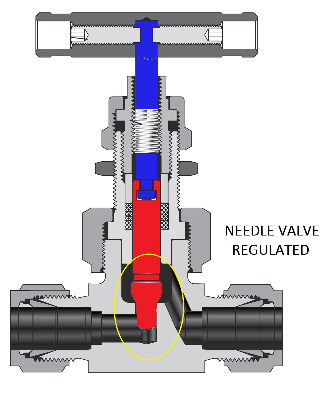
Regulated Fig 1
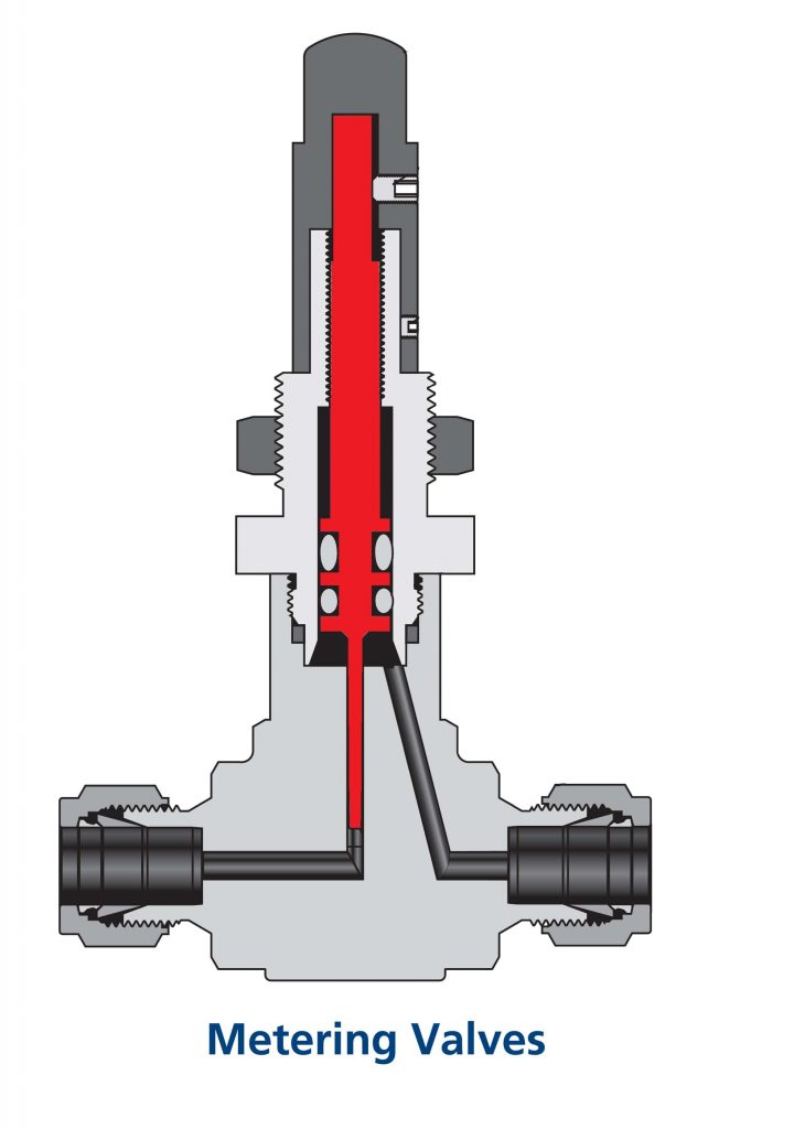
Metering Fig 1
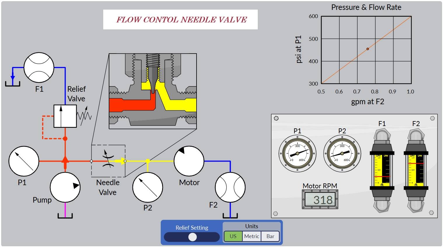
If we put it into a simple circuit, it allows us to control the motor speed by limiting flow.
Needle valve may be available with different stem geometries which may include ball, vee or plastic tips that will allow for shut-off functionality. Since the primary function of a needle valve is to regulate flow, if shut-off is required, one of these alternative stem tips should be considered. As a caution, if shut-off is attempted on a valve with a needle stem geometry, damage may occur. Fig 2 show Type of Stem of Needle Valve.
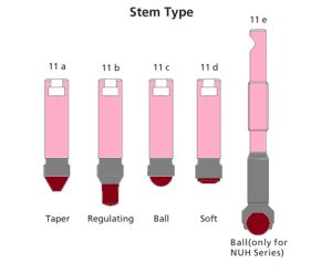
Fig 2 : Stem Needle Valve Design
Pressure Temperature Ratings Needle Valve
Pressure and temperature Valve ratings specify the maximum and minimum temperatures and pressures which the valve can be operate safe. These ratings are based on the properties of materials and used in pressure containing parts cause those of other materials that contact the system fluid. On design require and on performance tests. Design basis for our process and instrument valves, explains how pressure temperature ratings are determined. Its lists national codes and standards relating to valve ratings.

Selection Process System Parameters
These are some of the system parameters that should be considered during the selection process. It is important to consider the entire range of the parameters your valve may encounter.
- Pressure
- Temperature
- Media
- Flow
- Environment
- Energy Management
Pressure
Although we have already covered pressure, the concept of pressure differential is more appropriately discuss here with flow.
Delta P or pressure differential is the difference between the upstream and downstream pressure across a valve. Differential pressure is a natural aspect of a valves construction. A pressure drop will occur as system media is moving through a valve. For instance, a valve with a globe pattern will have a higher pressure drop across the seat than will a ball valve of similar size where the flow is straight through. The higher the pressure differential, the more or greater impact system pressure may have on wear of internal components.
What is illustrated through computational fluid dynamics or CFD, is a depiction of pressure drop across two different valve types. At the same flow rate, to achieve the same downstream pressure, shown in light blue, a higher pressure is needed on the inlet side of the globe pattern valve shown on the left. This is illustrated by a more extreme color gradient. The ball valve, or straight through pattern on the right will show less pressure drop, as indicated by the colors.

System Parameters
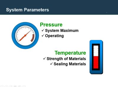
The first set of parameters we would like to look at is pressure and temperature. The reason why we put these two parameters together is that they effect each other.
The pressure a valve will see must be consider from various standpoints so we should understand the following:
System Maximum Pressure which is the maximum pressure this valve could possibly see.
Operating Pressure which is the normal operating conditions.
Another system condition that must be consider is temperature. Like pressure limitations, every valve has a maximum and minimum design temperature that should not be exceeded.
Strength of Materials – when the temperature elevates, the strength of materials decline. With valves, this usually means that as temperature goes up, the pressure rating goes down.
Sealing Materials – In many cases the pressure or temperature limiting component in a valve is the seal material.

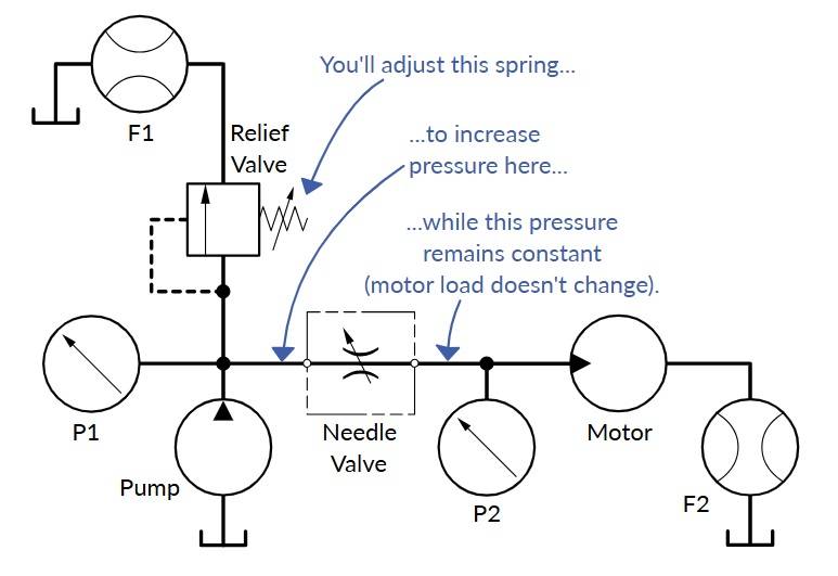
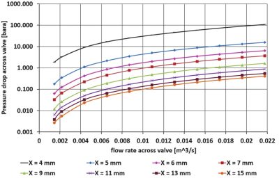
This time, you’re going to leave the flow control alone. (It has been arbitrarily set at about 50% closed.) Instead, you’ll adjust the pressure relief valve to induce different pressures, and cause a greater AP across the flow control. The relationship between pressure ahead of the needle valve, and flow allowed through the needle valve will be graphed.
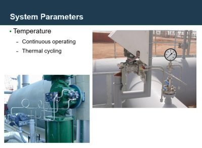
Temperature Continuous operating & Thermal cycling
Similar to pressure, you want to ensure that the temperature rating of the valve is sufficient for your application. There are two situations that temperature can have an effect for the selection process. The first is a continuous temperature where the environment of the valve and the system media is control and does not fluctuate. The second is a situation in which the environment in which the valve is place, is changing; or the temperature of the system media changes. An example of this is found with a valve that is place outside and will see temperature fluctuations from day to night, as well as season to season.
Media
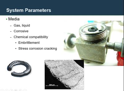
There are two primary forms of system media, gas and liquid. Media can come in the form of inert gases like nitrogen or argon or can be corrosive in nature such as hydrogen sulfide. When selecting a valve for a particular application, understand valve construction and how it relates to potential leakage. For instance, a metal to metal diaphragm seal may be more appropriate when dealing with toxic or corrosive gases rather than a soft-seated valve with a plastic or elastomeric stem packing.
Additionally, chemical compatibility should be a key consideration. Embrittlement and stress corrosion cracking may occur if the wrong material valve component is chose for your specific media. Be aware of chemical compatibility charts prior to selecting your fluid system components. (Reference commercially available corrosion and compatibility guides.)
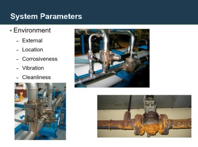
Environment
The next system parameter we will review is environment. It is important to consider the location of your valves. Will they be in a climate-control environment or outside expose to the elements. Additionally, the corrosiveness of the environment will have a major impact on the materials selected for the valve. Two extreme considerations would be valves:
exposed to salt-water air, such as an off-shore oil rig,
or pulping liquors in a pulp and paper press.
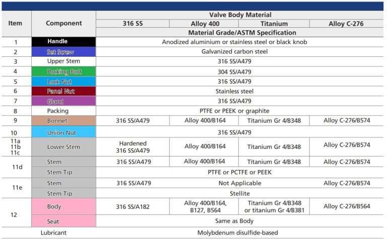
Material
The material of the Needle Valve body must be select with suit the needs of the application. Three most common materials are stainless is steel, brass and carbon steel. Also use alloys of nickel, copper, chromium, and others. Valves can made of plastic are available for certain applications. This type is choice of material is determine by compatibility with the system fluid, which encompasses such factors as corrosion resistance, pressure, temperature and cleanliness. Materials are purchase in accordance with specifications publish by the American Society for Testing and Materials (ASTM).

SIZE
The size of a Needle Valve often is describe by the nominal size of the end connections. A more important measure of size is the rate of flow of the valve can provide. Flow through valves or other fluid system components depends primary on component design, inlet and outlet pressures and fluid density. Flow coefficients (Cv) for each valve are publish in catalogs. in other words Cv values, deter mined by testing, and subsequent calculations are con duct it’s include with accordance with methods and formulas specified by the International Society for Measurement and Control (ISA).
STEAM SEALS
Stem seals will prevent leakage of system fluids from atmosphere.Therefore is available in several designs for suit different valves and applications. The system designers may select from these choices is to pre vent leaks or minimize system fluid loss, and reduce maintenance or cost repair. Selecting the optimum seal Furthermore increase system efficiency include lower total costs of ownership.
Conventional Packing
PTFE packing cylinder fits close around the valve stem. When tightening the packing nut forces the soft plastic material outward against the body.
We prevent leakage and minimize need for frequency packing adjustments by:
- Fine surface finishes on the stem shank is reduce wear of the packing as the stem slides during.
- Maintaining close tolerances it’s especial con centricity of the packing, stem, and bonnet
- Supporting the packing with metal or reinforced plastic glands and become prevent extrusion
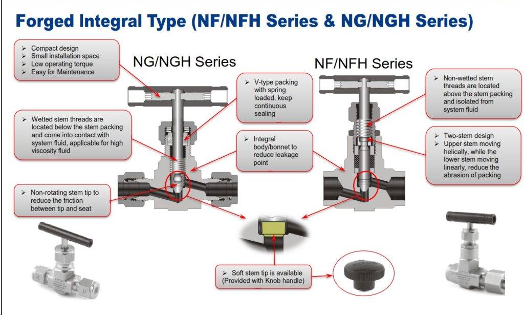
LIVE LOADED
Live Loaded Packing
Needle Valve Live loading maintains a constant pressure on the packing to ensure that it remains leak tight. This is especial valuable in applications with frequent temperature or pressure changes with high operating temperature. It’s eliminates the need for frequent packing adjustment and extends packing service life. The two most common methods of live loading are an elastomeric O ring seal or a Spring-loaded plastic packing.
The simplest live loaded seal is an elastomeric O ring. Elastomers from synthetic or natural rubber like materials which return to their original shape after being deformation. The resilience of the elastomer it’s provides the live load, which maintains until enough pressure on the seal to compensate for temperature or pressure changes and for wear.

Video

0:16
Selection Process Compliance and Testing
- Certified Material Test Reports (CMTR)
- Product Test Reports (PTR)
- Third Party
– TUV, NGV, ECE, CRN, METI, ASME N-Stamp
- Company Specification
–Lock-out ability
–Blow-out proof stems
- Important in the selection process is compliance and testing. The ability to offer proof sources showing compliance to industry standards and regulations, as well as product performance is an important consideration when selecting valves. These standards come in the form of governmental regulations, such as a Canadian Registration Number (CRN), a code such as ASME B31.1, or a company specification such as the ability to lock-out a valve.Facilitator’s Note: Utilize examples such as PTRs
Please Download our Tools Catalog for your referenc


