


Construction
Instrument Manifold consist of two-stem design needle valves and also have safety back seating seals functional in fully open position.

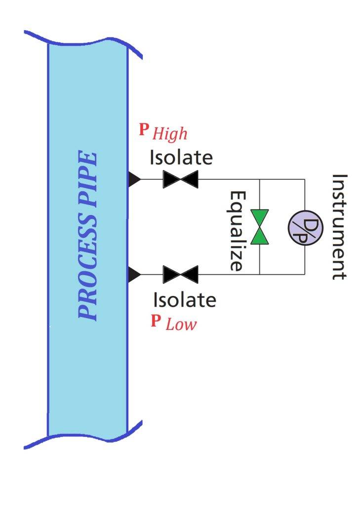
The high and low pressure chambers of a Transmitter have to be connected to the two process pressures whose difference ∆P to be measured. The connecting pipes are referred to as impulse lines. It is essential that the differential pressure at the process end of the impulse lines is transmitted to the dp cell without distortion.
At the dp cell end Transmitter of each of the impulse lines there should be an isolating valve, with an equalising valve connected across them. These valves can be installed individually or as a proprietary manifold which bolts directly onto the dp cell’s flanges. The advantage of the manifold arrangement is that it is more compact, easier to install and reduces the scope for leakage.
Dp cell end Transmitter of each of the impulse lines there should be an isolating valve, with an equalising valve connected.
Inlet from Process Line size is 1/2″ Female NPT connect to Manifold and Outlet 1/2″ Female NPT, with Venting 1/4″ Female NPT.
Dp cell (Transmitter) connected to the process line by its impulse lines objective of commissioning is to
successfully apply the differential pressure to be
measured to the dp cell (transmitter).
Presume that Phi and Plo are both large and that ΔP is small :
ΔP = Phi – Plo
Visual Manifold is show in below : Handle color codes for functions: Isolate/Block-Black, Equalize-Green, Test/Vent-Red.

Instrument Manifold Mounting Application
Manifold are specifically design for pressure transmitters of several brands generally that is Rosemount, SIEMENS, Honeywell. Normal connection references:
◎ Remote Mount Manifold Style (with transmitter)
FITOK Series: 2R, 2RH, 3R, 3RH, 5R, 5RH series manifold
Remote mount Manifold application is with or without mounting flange, is flexibility in mounting transmitters connection, which are design for safety, reliability and positive leak tight sealing of process fluid.
2-Way Valve Manifold :


3-Way & 5-Way Valve Manifold :


◎ Direct Mount Manifold Style (with Transmitter)
Direct Mount means The Instrument manifold Valve is design direct mount to Transmitter with three condition:
- Direct Mount Manifold (transmitter with coplanar mounting flange)
2D, 2DH, 3D, 3DH, 5D, 5DH series layout type A and type L manifold.
MSS SP-99 Flange for Instrument Transmitter Connection type.


2. Direct Mount Manifold (transmitter with traditional flange)
2D, 2DH 3D 3DH 5D 5DH series layout type V manifold
3. Direct Mount Manifold (transmitter without flange)
Integrated mount 2DSS-FNS8-C, 3DSS-FNS8-C-T, 5DSS-FNS8-C manifold only.
C Integral Manifold is specifically design for the pressure transmitters for Rosemount coplanarTM, including Model 3051C, 3051S, 2024 and 3095. It can be assemble directly to transmitters, eliminating the need for flanges.
Each of the following manifold contains four 7/16″ UNF x 2″ high tensile bolts.
Installation Instrument Manifold
We show some application for Instrument Manifold for liquid, Steam and Gas Instrument measurement.

Figure A: Liquid Fow Measurement.
Under low or zero flow conditions, entrained air or gas bubbles tend to flow along the top of a pipe and sediment settles at the bottom, so the tapping points are at the side of the pipe. The impulse lines are full of process liquor which transmits the differential pressure. The cell is mount below the tapping points so that any air bubbles rise into the pipe. The materials of construction of the dp cell and its diaphragm capsule must be specified carefully since they are in direct contact with the process liquor.

Figure B : Gas Fow Measurement.
Note that the tappings are on top of the pipe. If there is any possibility of condensate forming in the impulse lines they should slope down towards the tappings and up towards the dp cell. Any condensate collects in the catch pots which can be drain off intermittently.


Figure C & D: Steam flow measuring or other condensing vapours.
Best strategy is to accept that condensation is going to occur rather than try to prevent it. Thus the dp cell is operate with its impulse lines full of condensate which is use to transmit the differential pressure. Figures C and D show two arrangements, depending on whether the steam flow is in a horizontal or vertical pipe respectively. Because it could take a long time for the impulse lines to fill up by condensation, for commissioning purposes, filling tees are provided, which enable them to be topped up to the same level with water.
