


How to used Tube Bender
About FITOK Hand Tube Bender :
- FITOK Hand Tube Bender is used for bending Tubing and provides high quality performance in bending solutions.
- Read this operation manual carefully when using FITOK Hand Tube Bender.
- Ordering information :

Tubing Restrictions :
◎ FITOK Hand Tube Bender is available for bending tube of OD 1/4, 5/16, 3/8 and 1/2 in. and 6, 8, 10 and 12 mm in a variety of wall thicknesses;
◎ Tubing should be free of scratches and appropriate for bending.
Fractional Tubes
High-quality, cold-drawn or seamless carbon steel hydraulic tubing ASTM A179 or equivalent, with hardness equal to or less than 72 HRB (130 HV).
High-quality, seamless and austenitic stainless steel tubing ASTM A269/A213 (304, 316, etc.) or equivalent with hardness 90 HRB (200 HV or less).

Metric Tubes
High quality, cold drawn, carbon steel hydraulic tubing DIN 2391 or equivalent with hardness equal to or less than (72 HBR)130 HV.
High quality, seamless and welded Austenitic stainless steel tubing EN ISO 1127 (304, 316, etc.) or equivalent, with hardness equal to or less than (90 HRB)200 HV.


Fitting Installation:
Fitting Installation must be a sufficient length of straight tubing to allow the tube to be bottomed in the FITOK tube fitting when in- stalling fittings near tube bends.


Auxiliary Function of the Body Tube Bender:
The FITOK hand tube bender features a clamped position which allows the HTB to be clamped in a vice.
It is convenient when bending tube of hard materials or heavy-wall thickness, or long pieces of tube that need to be supported.

Bending Design :
FITOK HTB can be used to form single, offset and other bends. Measure and mark the tube prior to bending is contained in this section.
Measure-Bend Method
- Add the length of all sections together to estimate the overall length of tubing required.
- Mark the end of tube from which you begin the measurement for reference.
- Measure the desired bend length from the mark and make a bend mark at the corresponding point. This mark indicates the vertex of the bend.
- Bend the tube as the described in Use of the HTB, page 8.
- If additional bend is needed, take the vertex mark made previously for reference mark, and repeat step 3 and 4. (The vertex is where the center lines of the two legs of the angle intersect.)
Example of the method
A 90° bend 4 inches from the reference mark followed by a 45° bend with 4 inches between bends.

- Mark the end of the tube from which you begin the me- asurements for reference;
- Measure 4 in. from the mark made in step 1, and place a bend mark to indicate the first desired bend position ;
- Bend the tube 90° as described in Use of the HTB, page 8.
- Measure 4 in. from the vertex of 90° bend, and place a second bend mark.
- Place a directional mark over the second bend mark to ensure the bend is made in the intended direction.
- Bend the tube 45° as described in Use of the HTB, page 8.

Offset Bending :

In order to change the center line of the fluid, typically to avoid an obstacle, we choose an offset bend. To determine the length of offset bend, select the offset angle E first. Then, multiply the offset dimension O by the offset bend constant A.
L=O×A
Use this formula to calculate the distance between the bend marks described in Bending Design.

Example:
Offset angle E 45°
Offset dimension O 7.29 in. 7.29×1.414=10.31 in., or approximately 10 5/16 in.

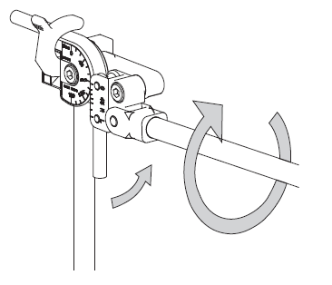
Use of the HTB :
- Swing the short handle up to the position above the body.
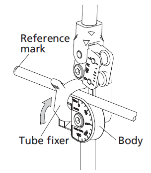
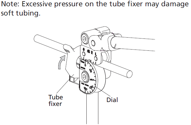
- Release the tube fixer.

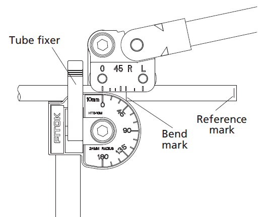
- Place the tube in the groove of the body with the reference mark to the left of the tube fixer.
- Fix the tube fixer on the tube just enough to hold the tube in positon. This restricts movement of the tube during initial positioning but still allows for additional alignment.
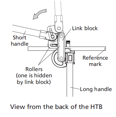
- Swing down the short handle carefully until rollers rest gently on the tube while keeping the link block parallel to the long handle.
Note: Non-parallel between link block and the long han- dle leads to premature bending.
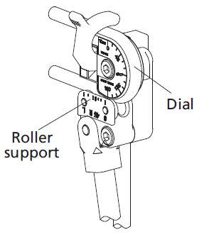
6. Align the zero on the Roller support with the zero on the dial.
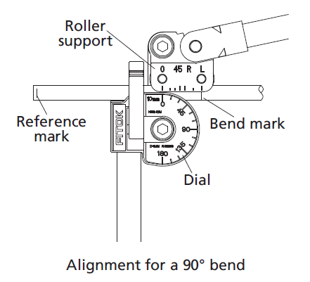
7. Align the bend mark with the mark on the roller support corresponding to the bend angle.
8. Push the tube fixer firmly over the tube to secure the tube in the groove of body.
Bending :
Bends 90° or less
- Slowly swing the short handle down until the 0 on the roller support reaches the desired angle mark on the dial.
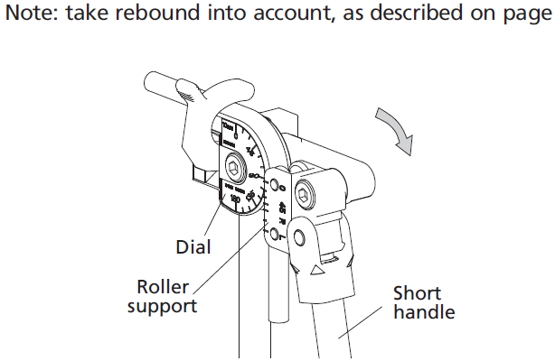
2. Swing the short handle away from the tube after completing the bend.
- Release the tube fixer and remove the tube from the HTB groove.
Bends greater than 90°
The right-angle design of the FITOK HTB offers maximum leverage when making bends. You can still use right angle leverage for bends greater than 90° based on the unique design of the HTB.
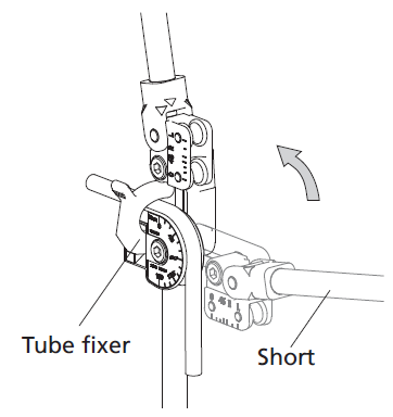
- Slowly swing the short handle down until the 0 on the roller support reaches the 90° on the dial.

2. Screw off the short handle from the U block until it will swing without moving the roller support.
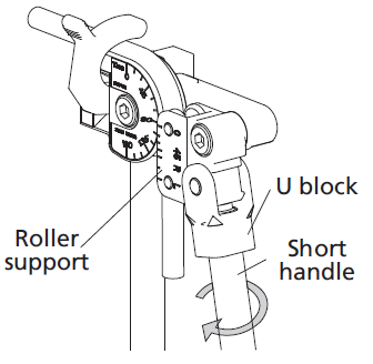
- Swing the short handle up until it is perpendicular to the long handle.
- Screw up the short handle. This structure will provide continuous right-angle leverage for the rest of bend great than 90°.
5. Continue the bending until the 0 on the roller support reaches the desired mark on the dial.
- Swing up the short handle away from the long handle after completing the bend, pausing when 0 on the roller support reaches the 90° of the dial. Screw off the short handle, move it until parallel with the long handle, then screw it up again.
- Swing up the short handle away from the tube.
- Release the tube fixer, and remove the tube from the bender.
Reverse Bending :
Sometimes, requirements of reverse bends exist. These are made with the reference mark to the right of the tube fixer.
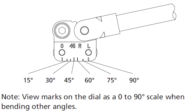
- Align the reference mark on the tube with the marks on the roller support as follows:
◎ Line up under the R mark for 90° bends.
◎ Treat the marks between 0 and R as an approximate 0 to 90 scale for other bend angles.
Bend the tube as described in Bending, page 10.
Rebound :
All tubing will exhibit rebound after a bend has been com- pleted. The amount of rebound relates to the tubing material, tubing wall thickness, the bend angle and radius.
Experience will be helpful in predicting the amount of reb- ound. Expect to allow 1 to 3° of compensation.
Note: Verify the bend angle using a protractor, template or against a known angle to ensure the desired bend angle has been achieved.

Note: When bending softer tubing such as aluminum or copper, do not bend all the way to the bend mark.
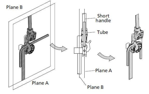
Bending on the Same Plane :
Make sure the bend is made in the right direction when making multiple bends on a single piece of tube.
When bends are in the reverse direction of the previous bend, aline the tube with the raised short handle (plane A).
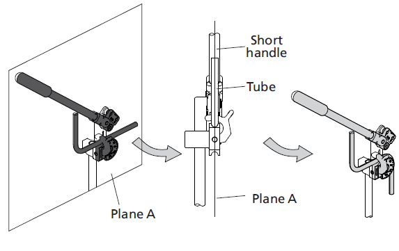
When bends are in the same direction as the previous bend, parallel the tube to the long handle (plane B).
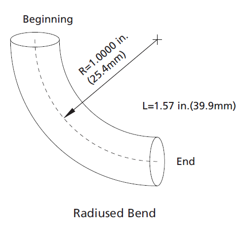
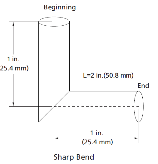
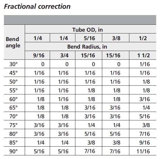
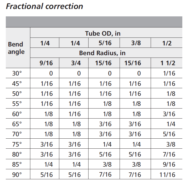
Correction (Gain) :
Correction (gain) is another available method to get the desired layout and it’s difference between the length of tubing used in the radiused bend and the length of tubing in the sharp bend, when measured from the beginning of the bend to the end.
Example:
1/4 in. tubing using a 1/4 in. bender with a 9/16 in. bend radius.
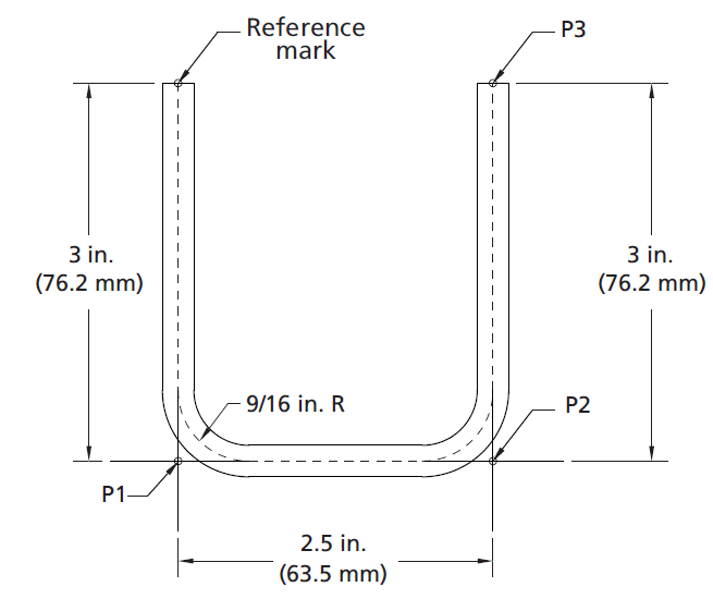
In order to get the needed bend, you can mark the tubing as follows : P1 = 3 in.
To confirm the location of the bend mark, add the new section length to the previous bend mark position, then minus the correction (gain) of the previous bend.
P2 = P1 + 2.5 in. – 5/16 in.(correction) = 5 3/16 in. P3 = P2 + 3 in. – 5/16 in.(correction) = 7 7/8 in.
7 7/8 in. is the total length of the tube.
90°correction = 5/16 in.
Bend the tube according to the description in Use of HTB, page 8.

We are PT. Solutec daya Mandiri is ready to serve you to provide Bender Tube and others Tools you can Contact us
